1 System overall design The coal mine safety monitoring system is mainly for the safety monitoring of the mine production system, including the monitoring of harmful or dangerous components (such as methane, carbon monoxide, etc.) in the mine air, the physical state of the mine air (such as wind speed, negative pressure, temperature, etc.) The monitoring, as well as the monitoring of the operating conditions of the ventilation equipment (such as equipment opening and closing, etc.), and in an emergency, can shut down some electrical equipment in the underground coal mine and stop running.
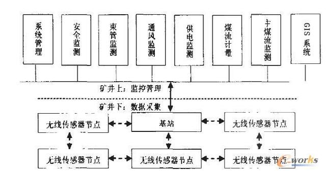
The system is divided into two parts, the uphole and the downhole. The downhole part mainly uses the sensor to collect the temperature and humidity and gas volume fraction information in the mine, and then transmits it to the base station through each node through routing; the uphole part is mainly responsible for receiving the data transmitted from the base station and processing it through each monitoring subsystem. , analysis, display data in the form of curves, graphs and reports, and support a variety of query statistics. The overall structure of the system is shown in Figure 1.

Figure 1 system structure diagram
2 Wireless sensor network design This system uses the ZigBee technology based on IEEE802.15.4 standard to form a wireless network. ZigBee is a short-range, low-power, low-cost, high-capacity, high-reliability wireless network technology. Its working frequency range is 2.405~2.480 GHZ. It uses direct sequence spread spectrum communication technology and the data transmission rate is 250 KB/ S, the wireless network data transmission module node capacity can reach up to 65000, each digital transmission module can communicate with each other, the distance between each network node can be unlimitedly expanded from the standard 75m, which is very suitable for the collection of coal mine underground information. The network node forms a mesh topology in a self-organizing manner, and each node can collect data autonomously, and the data is sent to the aggregation node through single-hop or multi-hop relay.
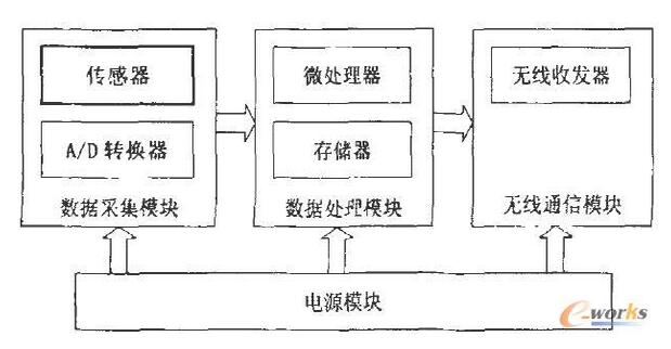
2.1 Wireless sensor network node architecture Wireless sensor network node is the basic unit of the network, responsible for data collection and transmission, its architecture consists of data acquisition module (sensor, A / D converter), data processing module (microprocessor, Memory), wireless communication module (wireless transceiver) and power module (battery, DC/DC energy converter) are composed of four parts, as shown in Figure 2.

Figure 2 Wireless Sensor Network Node Architecture
2.2 Sensor Node Design In the data processing module, the microprocessor is the core component of the sensor node, responsible for processing data and coordinating the entire system. In order to make the system have high performance, low power consumption, multi-model interface and other characteristics, this design finally uses the 8-bit single-chip ATmegal28L produced by ATME B as the microprocessor unit. ATmegal28L's advanced RISC architecture makes it a high computing performance HJ, not only has a universal interface such as UART, SPI, HC, but also has a multi-channel analog-to-digital converter. At the same time, its available open source development software tools are mature and sensor nodes. The operating system TinyOS supports it better.
Although the ATmegal 28L microprocessor comes with a 4KB EEPROM data storage area, it is necessary for the sensor node to have a relatively large, permanent data storage area for automatic update of the remote node code and nodes. The need to store more information, such as the preservation of configuration information. To this end, an additional 512K AT45DB041 non-volatile FLASH is used in the sensor node design as an external data memory.
In the wireless communication module, taking into account the data transmission rate of the wireless transceiver, the receiving and transmitting power, the energy consumption of the sleep, the start-up time and the signal modulation method, the CC2420 RF chip of Chipcon is finally adopted. The CC2420 RF chip is fabricated in a 0.18 urn CMOS process using SmartRF technology with minimal external components. Stable performance and low power consumption. Since TinyOS already includes CC2420 driver support, it is easier to connect to the microprocessor.
In the data acquisition module, the temperature and humidity sensor uses the SHTl1 chip, and the gas sensor uses the KGS-20. SHTI 1 is a highly integrated, low-power, high-precision, anti-interference digital temperature and humidity sensor chip from Sensirion. The chip converts humidity and temperature into electrical signals through two sensitive components. The electrical signal first enters the weak signal amplifier for amplification, then enters a 14-bit A/D converter, and finally outputs a digital signal through a two-wire serial digital interface. . KGS-20 type gas sensor is a semiconductor type gas sensor based on tin dioxide as a basic sensitive material. It is characterized by extremely high sensitivity and extremely fast response speed and power consumption. Low, very suitable for the detection of the fraction of flammable gas in the well.
In this system, in order to realize the communication between the base station and the host, a serial communication module is designed. The base station aggregates the data of each node and transmits it to the host through an RS232 serial interface, and the host processes the data.
3 Coal mine monitoring and management software design In- situ monitoring and management software includes eight subsystems: system management, safety monitoring system, beam monitoring system, ventilation monitoring system, power supply monitoring system, coal flow measurement system, main coal flow monitoring system and GIS system. The software is written in Borland's Delphi7.0. Microsoft Access 2003 is used as a back-end database. It can display various parameters such as table display, curve display, posture display and alarm statistics, as well as report generation and printing of various parameters.
3.1 System function design The safety monitoring subsystem is the core part of the entire coal mine safety production remote monitoring system. It is mainly used to monitor various environmental parameters such as underground environmental parameters and equipment opening and closing. After installing the sensors in some important locations, some environmental parameters and equipment start-stop status information can be directly reflected on the ground center station and the management network workstation, reducing the workload of the underground inspection and duty personnel, and helping the leader and dispatcher. Keep abreast of safety production and provide data support for command and dispatch.
The basic tasks of the ventilation system are: to supply sufficient fresh air in the well; to eliminate or dilute the toxic and harmful gases and dust in the mine; to mediate the climatic conditions of the mine, to create a good working environment; and to improve the resilience of the mine.
The power supply monitoring subsystem is used to display and query the bus voltage frequency of each substation under the underground, provide power equipment and the current power of various protection equipment. The completed functions include: real-time display of monitoring data of central substation, fan power distribution system, main inclined shaft power distribution system room; query historical monitoring data according to time, machine room, measuring point, etc.; Form some reports used by users.
The beam tube monitoring system can complete the inquiry and browsing of the monitoring data of the beam tube system by the leaders at all levels. The direction of the monitoring data can be visually visualized. The data items monitored every day have a fixed report format and can be queried. At least three gas samples are taken every day, and eight gases are taken at the same time. Through the analysis of the monitoring data, the risk analysis of the gas is carried out through the "triangle explosion-proof zone theory", and the results are obtained.
The GIS system is responsible for representing the mine safety geographic information system in two-dimensional graphics. It mainly includes graphic data system and attribute data system. The former mainly inputs, stores and queries graphic data (such as: point, line, surface and its topological relationship), and also has the functions of graphic analysis and output: the attribute data system is mainly completed. Attribute data input and management of graphic entities, output of various attribute data values, and the like. However, the two are not isolated, and the graphical data and the attribute data are dynamically connected through the data interface and the database server. The system mainly includes data input, graphic editing, graphic setting, graphic display, professional operation, data output, search query, model analysis and professional legend library. At the same time, it has various functions of the general GIS system, such as: zoom in, zoom out, modify, delete, move, rotate, copy, and so on.
The final functions implemented by the entire system include:
1) Collection of various sensor parameters: including environmental parameters (such as methane, carbon monoxide, temperature and negative pressure) and the collection of industrial and mining parameters.
2) Display of various sensor parameters: Various parameters collected by the collector are displayed on the liquid crystal display and computer of the collector respectively.
3) Over-limit alarm: When detecting the parameter over-limit of a certain sensor, the collector controls the buzzer to sound an alarm in time, and the computer simultaneously gives an alarm of sound and picture.
4) Power-off control of the equipment: When it is necessary to control the power-off of a certain equipment, the collector can operate the power-off device of the equipment to achieve control of the equipment.
5) Long-distance transmission of data: The parameters collected by each mine collector need to be transmitted to the ground central station for monitoring.
6) Recording and playback of various sensor parameters: The computer software stores various parameters transmitted from the lower computer in the hard disk space, and the staff can select any one of the parameters for recording and playback.
3.2 system module design system management: divided into three parts: user management, log management, code maintenance. User management is responsible for managing user information, including adding and deleting users, modifying user information, and assigning corresponding roles to users. The assigned role is responsible for assigning the appropriate roles to existing users of the system to limit and assign the operational privileges of different functional staff. The log management includes alarm log management and security log management, and the corresponding alarm log and security log can be queried through time.
The five systems of safety monitoring, ventilation monitoring, power supply monitoring, coal flow metering and main coal flow monitoring all have higher requirements for real-time performance, and the reflected data types are basically similar, so the system design these five modules into a unified function and display style. Each module has real-time display, safety monitoring, ventilation monitoring, power supply monitoring, coal flow metering, and main coal flow monitoring. The five systems all have high real-time requirements, and the reflected data types are basically similar, so the system will design these five modules. In a unified function and display style, each module has five function points: “real-time displayâ€, “real-time curveâ€, “data queryâ€, “history curve†and “reportâ€. "Real-time display" primarily performs real-time data display of important parameters that are closely related to safety or equipment conditions. The “real-time curve†mainly realizes dynamic curve drawing of real-time data of important monitoring points or parameters, so that the staff can visually see the trend of data changes, so that they can analyze the production status. “Data query†is the process of viewing some required data, including alarm data query and historical data query. Alarm data query can see some important alarm data. It can print important alarm historical data for easy reporting or self-analysis. deal with. The “history curve†mainly realizes the historical data drawing curve of the monitoring parameters that are important for a period of time, so that the staff can see the trend of the historical data very intuitively, so that they can analyze the production status. “Report†is based on the needs of the enterprise, sorting and counting some key data, forming an intuitive written document for easy storage and printing, and providing convenience for the work of the enterprise.
Because the beam tube monitoring is not required for real-time performance, it is different from the previous system functions. It is divided into four functions: “data queryâ€, “curve analysisâ€, “report query†and “triangle explosion-proof zoneâ€. The “data query†is to query the concentration content of all gases in the form of a table by measuring the position of the point and selecting the start and end dates. “Curve analysis†is a graph of the concentration percentage of each sampled gas at a fixed time by date and measurement point. “Report Query†is a daily report of “Yangchangwan Coal Mine Beam Tube Monitoring and Analysis Dailyâ€, which can be queried by date. The “triangle explosion-proof zone†is able to query all gas sampling records in the explosion danger zone, and can display the analysis chart and analysis results of each sampling record, and locate the results on the analysis chart.
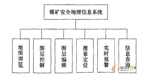
The "GIS system" is divided into six functional modules from the overall function: map browsing, layer control, layer editing, search positioning, real-time alarm, and information query. The overall system function is shown in Figure 3.

Figure 3 Coal Mine Safety Geographic Information System Function Block Diagram
3.3 System Database Design The database of “Coal Mine Safety Monitoring System†should include the main systems for underground monitoring: power supply, drainage, main coal flow, ventilation, beam tube, security inspection, and also add a library capable of GIS (Geographic Information System) development. Table information and library table information for system management. When designing the table structure, taking into account the characteristics of this monitoring system, the monitoring data of security inspection, ventilation, alarm and other modules are separately constructed.
4 Conclusions This paper studies the composition, architecture and hardware and software design methods of wireless sensor network coal mine safety monitoring system. The system combines ZigBee wireless network technology with traditional coal mine safety monitoring system to make up for the limitations of the underground monitoring network relying on wired transmission, so that the safety monitoring system can effectively cover the hidden dangers of accidents, and the mobile equipment for continuous mining work surface On-grid provides technical support. The technology can easily realize the seamless interface between the wired network and the wireless network, and provides an important reference for the implementation of the hybrid network.
Passenger elevator refers to the elevator designed for transporting passengers, which requires perfect safety facilities and certain interior decoration. It is divided into low speed ladder, medium speed ladder and high speed ladder. China Passenger Elevator,Residential Passenger Lifts manufacturers, welcome Electric Passenger Lift,Passenger Elevator Lift purchasers from worldwide to visit our site.
Passenger Elevator,Residential Passenger Lifts,Electric Passenger Lift,Passenger Elevator Lift
Suzhou Stable Trade Co., Ltd , https://www.stable-elevator.com