Rubber is a non-metallic material with some unique mechanical properties, such as extremely high elasticity, which is not damaged under great deformation, but its strength is very low. The mechanical properties of soft rubber and hard rubber are also very different. For flexibility, soft rubber is about 1,000 times higher than hard rubber. Production practices have proven that cutting tools are used to cut rubber. It is prone to sickle, serrated chips, and rough surface of parts. However, according to the special mechanical properties of the rubber, after using the special structure of the tool and the corresponding cutting amount and other technological measures, it will receive satisfactory processing results.
1. Process analysis of parts
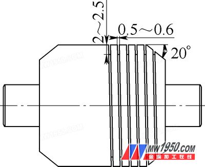
Figure 1 Parts schematic
Figure 1 shows the processing of a certain aerospace product by our company. The material of the part is rubber HG1142 material. The main characteristics of this material are as follows:
(1) The rubber has good elasticity during processing, and the deformation is large during cutting, and the processing size is difficult to control.
(2) Thermal conductivity and heat resistance are poor during rubber processing. When the cutting temperature exceeds 60 to 150 ° C, it is deteriorated, melted, and odor is generated.
(3) The rubber has low strength and high toughness, and the cutting edge of the processing tool is required to be as sharp as possible.
(4) There are many impurities in the industrial rubber roller, and the cutting edge of the cutter is easy to crack.
2. Tool design
According to the processability analysis of the parts of Fig. 1, the geometric angle of the tool is different according to the tool for processing rubber compared with the tool for processing metal materials. Due to the special technical requirements of the rectangular thread of the rubber roller processed by the part, the bottom surface of the groove is deep. The thread surface needs to be smooth and smooth, and the combined turning tool for processing rectangular thread is shown in Fig. 2.
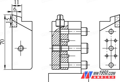
Figure 2 schematic diagram of the combination turning tool
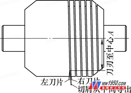
image 3
The main feature of the tool is that the turning tool is composed of two left and right cutters. In this configuration, the left cutter has only one straight edge, while the right cutter has a 90° edge. When the left and right cutters are combined, a "door" edge is formed, and the chips can be led out from the middle of the two cutters as shown in Fig. 3. The tool has a small wedge angle of 8° to 10°, so the cutting edge is sharp and the cutting is light. The left cutter has an outer slope of 10° and an inner slope of 2° and must be tilted to the left, as shown in Figure 4.
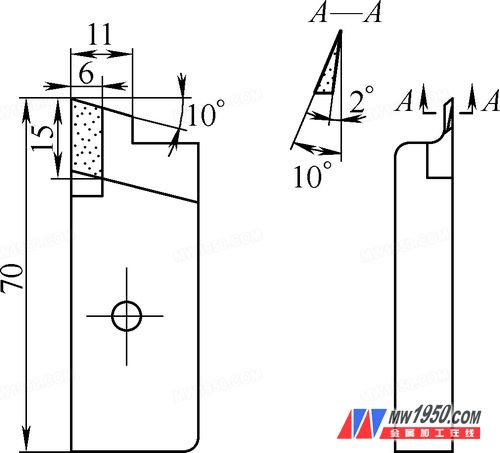
Figure 4 left cutter
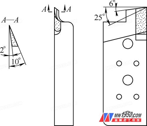
Figure 5 right knife
The outer side and the inner side of the right cutter are also inclined by 10° and 2°, respectively, but must be inclined to the right, and the back angle of the top edge is 6°, and the inner side is inclined by 25°, as shown in Fig. 5.
The left and right cutters are made of welded cutters, the blade material is YG8, the blade is ground, and the cutter body is made of 45 steel.
3. Use of the tool
After the left and right cutters are assembled, a gap of 0.03 to 0.05 mm is left between the blades of the two blades to prevent the blade from colliding.
Since the processing material is rubber, the workpiece thread has elastic recovery after processing, and the groove width is enlarged by 0.1 to 0.15 mm when sharpening the turning tool.
In order to reduce the friction area between the outer surface of the two cutters and the thread surface to reduce the cutting resistance and the elastic deformation of the workpiece, the turning tool should be installed at a distance lower than the center of the workpiece. The amount of reduction H is calculated according to H=0.707R (R is Rubber roller outer circle radius). According to the relationship of the H value, the infeed depth t of the turning tool during machining should be larger than the profile depth h of the thread, and the value can be calculated by t=1.414h.
In order to reduce the cutting temperature, improve tool life and machine surface roughness, compressed air cooling must be used for cutting.
Before the machining, the chamfering of the car at the end of the rubber roller is 20°, so that the cutter cuts into the workpiece from shallow to deep, and gradually cuts in, and obtains stable guidance.
4. Conclusion
Through the analysis of the performance of the rubber, according to its processing characteristics, the design of the processing tool meets the requirements, meeting the processing requirements.
Loader Parts,Track Loader Parts,Case Loader Parts,Skid Loader Parts
JINING SHANTE SONGZHENG CONSTRUCTION MACHINERY CO.LTD , https://www.sdkomatsuexcavatorparts.com