Abstract: The tool and workpiece information are analyzed. The tool pose matrix is ​​used to describe the relative motion between the tool and the workpiece, and the tool pose matrix is ​​realized by the motion cascade matrix. The motion function of the tool is given. The main steps of the design, this method can be used to find all possible machine motion function solutions. Taking the design of a three-coordinate machine tool motion function scheme as an example, the method is effective.
1 Introduction
The design of machine tool motion function is the first work to be done in the design of machine tool. The traditional design method of machine tool function is based on the existing machine tool design examples for experience and analog design. This method is simple, but the innovation is poor, which is the main reason for the simplification of current machine tool products. With the development of the economy, the demand for products in the market is multi-variety and small-volume. In order to meet the needs of the market quickly and economically, it is necessary to theoretically study and establish a design method of machine tool function that does not rely on prior knowledge. This is of great significance for the new machine design. This paper introduces a method for machining surface information based on tool and workpiece and analyzing the motion function of the machine tool through analysis, that is, the creative design method of machine tool motion function. The application of this method in 2D surface machining has been introduced in [1]. This paper will introduce the further research results of this method, and take a three-coordinate machine tool as an example to introduce the whole process of the design of its motion function scheme.
2 Tool workpiece information description method
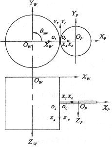
The basis of the creative function design method of the machine tool is the concept of the cutting surface of the tool [1] . The cutting surface of the tool refers to the surface of the tool that can be in contact with the surface to be machined. It is a generalized surface, which can be points, lines, Face (depends on the type of cutting surface). For the case where the face milling cutter shown in Fig. 1 processes the outer cylindrical surface, the cutting face of the tool is a circular line around the axis of the tool; if it is a cylindrical milling cutter, the cutting face is a cylindrical surface; if it is an end milling cutter, the cutting thereof The surface is a flat circle, and so on. At this time, the cutting surface of the tool is created by the rotary motion of the tool itself, and the cutting surface of the tool only needs one rotary motion.

Fig.1 Schematic diagram of the outer cylindrical surface of the chip milling cutter
Next page
Calcined aluminum flap discs are made by calcined aluminum coated cloth, one kind of the flap discs or power flex discs. Flap discs have the advantages of grinding discs and fiber discs, making it easier for grinding and polishing disposable, reducing the work process and lower the grinding cost. Especially, calcined aluminum flap discs are widely used in grinding and polishing general metal, stainless steel, alloy and so on.
Abrasive grains for Flap Disc can be Aluminum oxide, calcined aluminum, silicon carbide and zirconia. Flap discs have the features of quick speed, high efficiency, synchronous consumption, strong grinding force, fast heat disspation and good performance.Calcined Aluminum Flap Disc,Aluminum Flap Disc,Aluminum Oxide Flap Wheel,Aluminium Oxide Flap Wheel
Henan Yuteng Abrasives Co.,Ltd , https://www.henanyutengabrasives.com