2.1 Mathematical description of the cutting surface of the tool
The cutting surface of the tool is described in the form of a homogeneous function matrix [2] . In Figure 1, O P is the cutting plane coordinate system, O C is the coordinate system of the cutting surface point, and the X C coordinate points to the physical material direction of the tool, r Is the radius of gyration of the tool. This allows the cutting surface of the tool to be described in the O P coordinate system as follows:
 (1)
(1)
Where C γ P =cos(γ P ), S γ P =sin(γ P ), {x C } C is the coordinate array of points in the O C coordinate system, and {x C } P is in the O P coordinate system The coordinate array of points, [T PC ] is the description matrix of the cutting face of the tool.
2.2 Mathematical description of the machined surface
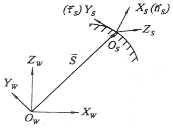
It is still described in the form of a homogeneous function matrix. As shown in Fig. 2, O W is the workpiece coordinate system, O S is the coordinate system at a point on the machined surface, the X S coordinate points to the outer normal of the machined surface, and the Y S coordinate is the tangential direction of the bus bar of the machined surface. This way you can find a description of the machined surface in the O W coordinate system:
 (2)
(2)
Where [ W T S ] - the description matrix of the machined surface

Figure 2 workpiece machining surface description coordinate system
Previous page next page
Galvanized Metal Watering Can,Galvanized Striped Large Watering Can,Galvanized Steel Watering Can,Semi-Circular Galvanized Metal Watering Can
xiacun factory , https://www.xiacunmetal.com