Abstract: The causes and hazards of the transformer's biasing in the full-bridge inverter arc welding power source are analyzed. The principle and method of preventing the biasing in the primary side of the transformer or setting the automatic correcting circuit are described.
Key words: full-bridge inverter power supply; transformer bias; blocking capacitor;
Foreword
Due to the large capacity of the arc welding transformer, most of its inverter circuits are full bridge type. In such an inverter, the transformer core operates in a bidirectional magnetization state, and the magnetic flux in the core alternates in one or three quadrants centered on the origin, and the magnetic flux can be automatically reset. That is to say, the ideal working state is that the magnetic flux of the transformer is symmetrical about the origin, and the magnetic flux in the core maintains an equilibrium state. However, due to the influence of feedback circuit, control circuit, drive circuit and power main circuit, the positive and negative square waves on the primary side of the transformer are different, so that the transformer is biased.
The biasing will increase the power consumption of the transformer, reduce the efficiency, and increase the temperature rise. Eventually, the transformer core will be saturated and the power switch will be damaged, and the inverter will fail. Therefore, in the design and use, it is necessary to attach great importance to the bias phenomenon of the transformer and take effective protective measures.
1 Causes of bias generation
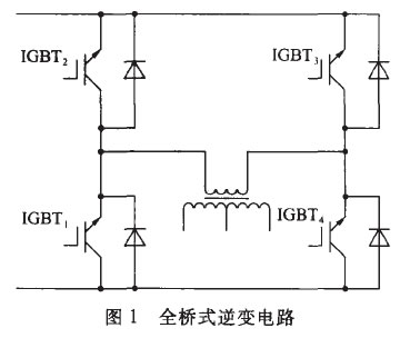
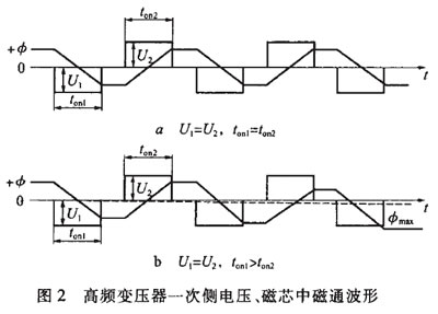
The full bridge inverter circuit is shown in Figure 1. The power switch tubes TGBT1, TGBT3 and TGBT2, TGBT4 are alternately turned on and off during the first half and the second half of the duty cycle. If their saturation voltage drops are equal and the turn-on time is the same, the operating state of the circuit is balanced. In other words, the condition of the flux balance is equal to the area of ​​the volt-seconds applied in both the positive and negative directions on the primary side of the transformer, as shown in Fig. 2a.

The relationship between the voltage U on the primary side of the transformer and the magnetic flux φ in the magnetic core is 

When the voltage U is constant, the magnetic flux φ will increase linearly with time.
For the waveform shown in Figure 2a, when IGBT1 and IGBT3 are turned on, the voltage applied to the primary side of the transformer U1 decreases linearly from the maximum positive value +φ, crossing the zero point at 1/2on1, and reaching the negative maximum at the end of conduction. The value -φ is zero when the bridge is cut off, the voltage applied to the primary side of the transformer is zero! The rate of flux change will also be zero, that is, the flux will remain -φ until the second half of the cycle starts IGBT2 and IGBT4. At the time of conduction, at this time, the voltage U2 applied to the primary side of the transformer is opposite to the direction of U1, the magnetic flux changes from -φ to the opposite direction, crosses the zero point at 1/2on1, and reaches +φ at the end of conduction. In the equilibrium state, the number of volt-seconds applied in the two half cycles of the primary winding N1 of the transformer is the same, that is, the flux of U1*ton1=U2*ton2 is naturally also symmetrical.
Due to the difference in saturation voltage drop of the power switch tube, the voltage applied to the transformer in the positive and negative half cycles is not equal, and the storage time of the power switch tube is inconsistent, the pulse width of the output of the control circuit is inconsistent, and the feedback loop does not cause Symmetry and the like may cause the conduction pulse widths of the power switch tubes to be unequal. These will form volts and seconds in both positive and negative directions, making the power conversion circuit operate in an unbalanced state.
In Fig. 2b, U1=U2, ton1>ton2, because the magnitude of the change of the magnetic flux during the ton1 time is large, the amplitude of the magnetic flux change is small, and the magnetic flux cannot return to the starting point at the end of one cycle, so in one direction Gradually increasing, the working area will be biased to a quadrant, so that the transformer core gradually enters saturation state, the inductance of the primary side of the transformer is reduced to a small extent, and the current of the drain 6 of the collector 5 of the power switch tube has a large peak. The overcurrent of the power switch tube increases the power consumption and increases the temperature rise. As a result, the characteristics of the power switch tube are more unbalanced, the transformer core is more saturated, and a larger peak current is generated. This vicious cycle until the power switch The tube is damaged by thermal breakdown.
Next page
Compared with single-channel pipettes, multi-channel pipettes simplify all the tasks associated with microtiter plates that often occur in immunology, biochemistry, clinical diagnosis and food analysis. Multi-channel pipettes generally have 8 and 12 heads. The gun body can be rotated at 360°C, and each part can be disassembled and repaired separately. The lower half can be sterilized at 121°C. The dimpled housing ensures a firmer grip for the operator. Can be quickly calibrated.

how to use multi channel pipette,best multi channel pipette,multi channel pipette for 384 well plate
Yong Yue Medical Technology(Kunshan) Co.,Ltd , https://www.yonyue-pcrtube.com