New Chinese-style foyer decoration design points New Chinese-style foyer decoration taboo
Abstract: In order to reduce the processing cost of special rotary milling cutter, a general mathematical model of the cutting edge curve of special rotary milling cutter based on non-CNC machining scheme is given. The realization method of axial and radial relative feed motion is discussed and given. An example of the solution for two typical special rotary milling cutters.
1 Introduction
The special rotary milling cutter is an indispensable tool for machining free-form surface workpieces such as aerospace parts and metal molds. It can be used with CNC machine tools or machining centers to achieve high-quality, high-efficiency machining. With the development of CNC machining technology and the increasing complexity of machining objects, the application range and consumption of special rotary surface tools are increasing. At present, the special rotary surface cutters mainly use multi-axis linkage CNC grinding machines. Because the equipment is expensive (about one million CNC grinding machines are imported, it costs about one million US dollars), so the manufacturing cost is high. If the existing common tool grinding machine can be used to realize the non-CNC machining of the special rotary surface tool, the manufacturing cost of such a tool can be greatly reduced. This paper presents a general design model based on non-CNC machining schemes suitable for large-scale machining of different types of special rotary milling cutters, and discusses the implementation of axial and radial relative feed motion. The author has successfully manufactured a ball-end spiral milling cutter using a non-CNC machining program. This article is a general application of the previous work.
2 General mathematical model of the cutting edge curve
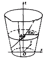
The working profile of the special rotary milling cutter is the rotary surface, and the spiral cutting edge curve on the rotary surface (see Fig. 1) is defined as the oblique running line with the fixed angle on the rotary surface. The equation can be expressed by the general formula.
r ={x,y,z}={f(u)cosv,f(u)sinv,g(u)} (1)

Figure 1 Spiral cutting edge curve on the rotating surface
Where u and v are parametric variables; f(u) is the radius of gyration of the plane of revolution, f(u) ≥ 0; v is the angle between f(u) and the positive direction of the x-axis.
In order to find the oblique line on the rotary surface, the first basic quantity must be solved first. Available from formula (1)
r u={f(u)cosv,f(u)sinv,g(u)}
r v={-f(u)sinv,f (u)cosv,0}
So there is
E= r u2=f2+g2
F= r u· r v=0
G=f2
The tangent vector at any point on the oblique line is dr, and the warp tangent vector passing through this point is d r . Considering that for the warp dv=0, there is
d r = r udu| r vdv
d r = r udu
Since the oblique line has a certain angle j with the warp, the angle between d r and d r is a fixed value j, and the angle is calculated as
Cos2j=( d r ·d r )2= Edu2
|d r ||d r | Edu2+Gdv2
Available after finishing
Esin2jdu2=Gcos2jdv2 takes positive roots
Dv=tanj(E/G)du=tanj[(f2+g2)/f]du (2)
After the points
v=tanj ∫ u (f2+g2) du+C
U0 f
(3)
In the formula, C is given according to the initial conditions of the specific problem, and the continuous condition between the different turning surfaces of the cutting edge curve is the initial condition.
Substituting equation (3) into equation (1) yields a general mathematical model of the edge curve with only one parameter and a fixed angle j with the warp.
Next page
Pmma Slight Led Mirror Light,Chrome Makeup Mirror,Chrome Led Mirror,Erp Certificate Of The Mirror Light
NINGBO EASTKEY ILLUMINATE APPLIANCE CO.,LTD , https://www.eastkeylighting.com