(1) The system adopts SIEMENS840DNCU571.4.
(2) The human-machine interface uses OP010 and the hard disk PCU50.
(3) The drive adopts the 611D system, and the motor uses the 1FT6 and 1PH7 series servo motors, as follows:
Y-axis: 1FT61021AC714EG1, 23N·m, 2000r/min, built-in absolute encoder. B axis: 1FT61088AF714EG1, 37N·m, 3000r/min, built-in absolute encoder. C axis: 1FT61021AC714EG1, 23N·m, 2000r/min, built-in absolute encoder. SP axis: 1PH71632ND030BD2, 210.1N·m, 1000r/min, built-in incremental value encoder.
(4) Capacitor module value is 20μF, order number: 6SN11121AB000CA0.
(5) When the external power supply is out of power, we also need to ensure that the system can process the program in a short time, and remind the machine operator of the machine working state. Therefore, we also designed the UPS power supply for controlling the power supply DC24V on the hardware. System control is effective when external power is off. The specific models are: power module 6EP19312EC01, 7AH battery 6EP19356ME21. The connection circuit diagram is shown in Figure 3:

image 3
In Figure 3, -GD1 is the SIEMENS modular power supply unit PowersuppliesSITOPpower, the specification is 3-phase AC380V input, and the output is DC24V, 20A. All DC24V control power supplies of the machine tool are provided by it. The DC24VUPS power supply control module is connected in series with its DC24V output terminal, and the DC24V is output to the control loop of the machine tool through the UPS power supply control module. A 7AH battery module is also connected in series on the UPS power control module side. The UPS power control module can quickly supply the battery module power to the machine control loop at the moment of power failure, and the power supply of the NC part can be guaranteed within a certain period of time. Allow machine operators to handle real-time conditions. We also brought up an operational message (battery normal I36.0) and a fault message (battery not ready for I36.1) on the UPS power control module to allow the machine operator to better handle the relevant information.
3. Design of software program
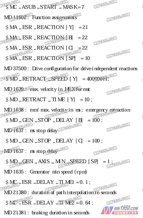
The design of the software program is to timely process various information by writing corresponding programs, and strive to meet the design requirements of the machine tool quickly. The implementation of the "power-off back" function can be implemented in a variety of ways, such as direct control of the axis through the drive parameters, and control by the NC. Because we are designing the "power-off and retreat" function is controlled by NC, there is no special preparation in the PLC program, mainly reflected in the NC parameter of the machine tool and the compilation of the G code.
(1) The setting of NC parameters is based on the design of machine parameters. Because the key point is the realization of the function of “power-off and retreatâ€, we will not elaborate on the parameters of the machine axes and channels, mainly with “power off. Refer to the parameters related to the "Return" function:

Previous page next page
I-pulse feeder units are distinctively fabricated for I-pulse SMT pick and place machine models. I-pulse feeder designs are fitted to provide accuracy during component feeding process. I-pulse feeders are also capable of minimizing component loss. Our company provide good quality I-pulse feeder and we assure you that all our SMT feeders are well maintained and undergo strict quality assurance process before releasing it to our customers. Feel free to contact us for any inquiries regarding I-pulse feeder products and our customer support personnel are always on-line to provide answer.
Ipulse Feeder,IPulse Tape Feeder,IPulse Component Feeder,IPulse M1 Tape Feeder.Yamaha i-pulse Feeder
ShenZhen KDW Electronics Co.,Ltd , https://www.smtsplicetape.com