Abstract: Aiming at the problems of traditional video surveillance system, such as blind monitoring area and low work efficiency, this paper designs a video surveillance system for crowd abnormal activities based on wireless sensor network location technology. Firstly, according to the wireless signal reception intensity indication (RSSI) method, the function relationship between the received signal strength indication and the receiving distance is obtained through experiments, and the motion trajectory of the monitored personnel is obtained by the curve fitting technique, and then the filtering noise technology is used to filter the trajectory noise data. . Secondly, the design idea of ​​non-security domain is proposed. If the system finds that the monitored personnel appear in the non-security domain, it will automatically trigger the alarm and record the scene. Finally, a prototype system was designed and implemented, including the underlying sensor node hardware programming, middle layer message processing and upper layer data processing modules. The experimental results show that the system can accurately locate the active position of the person and automatically trigger the alarm when abnormal activity occurs.
0 Preface
Video surveillance systems play an important role in the real-time monitoring of key sectors or important locations in various industries.
The management department can obtain effective information such as images or sounds, and monitor and record the process of sudden abnormal events in real time to help on-site forensics and timely arrange police handling cases.
With the popularity of the Internet, the rapid development of computers, image processing, and transmission technologies, video surveillance technology has also made great progress. High-intelligence, high-efficiency, high-security video surveillance systems have become an inevitable trend in domestic and international development.
At present, research on video surveillance systems is mainly focused on data transmission and terminal display. The literature uses GPRS to transmit data captured by the public lighting video surveillance system and display it at the terminal. The literature designs a wireless monitoring system with self-organizing jump data transmission. The paper proposes a device monitoring system based on ZigBee wireless communication technology. However, the terminal of the existing video monitoring system only relies on the staff to frequently switch the monitoring screen to monitor the scene, which not only reduces the working efficiency of the monitoring system, but also makes the screen that has not been switched into a monitoring blind zone. In addition, the existing monitoring system is very There is less automatic alarm function, which is also the direction that video surveillance systems need to focus on.
Based on the wireless sensor network positioning technology, this paper designs a video surveillance system for crowd abnormal activities. The system can accurately locate the active position of the person. When an abnormal activity occurs, the alarm function is automatically triggered. The system staff only needs to process the scene after receiving the alarm information, thereby improving the working efficiency of the system. This paper starts with the key technologies and difficult problems of the system. Firstly, the problems existing in the practical application of the ideal state relationship model of received signal strength indication and distance are obtained. Through design experiments, a large amount of data is obtained, and the curve is fitted to obtain the received signal. The relationship between intensity indication and distance. Then, based on the problem that the sensor node position information is affected by the unstable power supply of the node and other noise data, a filtering technique based on the expected value and threshold is designed to filter the noise data. Secondly, the design idea of ​​non-security domain is proposed. If the system finds that the monitored personnel appear in the non-security domain, the alarm will be triggered automatically. Finally, a prototype system was designed and implemented, including the underlying sensor node hardware programming, middle layer message processing and upper layer data processing modules.
1 system key technology and difficult issues
1.1 Obtain the correspondence between RSSI and distance values
The Received Signal Strength Indicator (RSSI) estimates the distance between nodes by the attenuation of the signal during propagation [8]. Since the signal strength decreases during the propagation of the signal, the distance of the transmitter can be estimated based on the received signal strength of the receiver. The mathematical model of the wireless channel is as shown in equation (1).

In equation (1), d is the distance between the transmitter and the receiver, d 0 is the reference distance; n p is the channel attenuation index; generally takes the value 2-4; p 0 is the signal strength from the transmitter d 0 ; P(d) is the signal strength from the transmitter d; p 0 can be derived empirically or from a hardware specification. From this equation, d can be found from the signal strength P(d).
However, the channel is time-varying due to the effects of multi-path fading and non-of-sight blockage. In certain environments, the signal is severely deviated from the above model. The estimated distance d has a large error.
Therefore, the relationship between the RSSI value and the distance in an ideal state is not applicable to the system. This paper must find the functional relationship between the RSSI value and the distance in the experimental environment, which is a key and difficult point in the work of this paper. Through research and analysis, this paper designs an experiment to obtain the relationship between RSSI and distance in the experimental environment. The experimental scheme is shown in Figure 1.
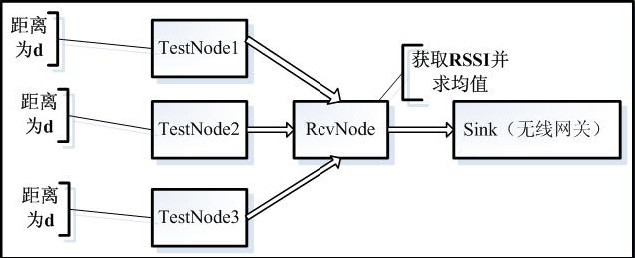
Figure 1 RSSI and distance relationship acquisition experimental scheme
When the distance is d, the three TestNode nodes respectively send 40 data packets to the RevNode, and the RecvNode node extracts the RSSI values ​​in the received 120 data packets and averages them. The experiment is repeated 10 times, and then all the average values ​​are performed. Find the mean, as shown in Figure 2.

Figure 2 RSSI value of anchor node 2 when the distance is 1 meter
It is thus easy to know that each distance d corresponds to an RSSI mean. After summarizing all the data, the relationship between the RSSI and the distance is as shown in Fig. 3.

Figure 3 Relationship between distance and RSSI
1.2 Curve fitting
In this paper, we use the exponential fitting and polynomial fitting method in curve fitting to find the function relationship. It is best to obtain a cubic polynomial fit through a series of experiments and calculations. The function expression obtained by fitting is shown in Equation 2.

Figure 4 shows a comparison of the distance and the RSSI relationship between the cubic polynomial and the exponential fitting. It is obvious from the figure that the curve fitted by the cubic polynomial is more consistent with the actual situation.
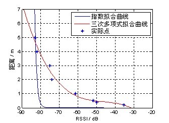
Fig. 4 Comparison of distance and RSSI relationship between cubic polynomial and exponential fitting
1.3 Correction processing
Since the wireless sensor node is subject to environmental factors, the RSSI value correction process is performed before the calculation of the received RSSI value. First, set the minimum and maximum critical values ​​of the RSSI value. When the experimentally measured RSSI value is much smaller than the minimum critical value, it is equal to the minimum critical value, or the RSSI is much larger than the maximum critical value to make it equal to the maximum critical value. Value, if the RSSI and the critical value are not much different, the RSSI value is appropriately corrected according to the experience gained from the experiment, so that the RSSI value returns to the inside of the critical region.
1.4 Filtering
Step 1: Set the expected value of RSSI, as shown in equation (3):

Where R 0 is the expected RSSI value, R is the actual RSSI value, R 1 is the previous RSSI value, and R2 is the second RSSI value obtained before, α, β, γ are respectively R The weights of R 1 and R 2 in the expected values ​​are set to 0.6, 0.25, and 0.15, respectively.
Step 2: Set the threshold. The threshold is set and summarized on the basis of a large number of experiments. The system is set to 0.5.
Step 3: Denoising, if the absolute value of the expected value 0 R and the current value R difference is less than the set threshold, let the last value be the current value, R = 1 R and 2 R = 1 R; if expected If the absolute value of the difference from the current value is already greater than the threshold, the expected value is taken as the current value, R = R 0 , and R 2 = R 1 , R 1 = R 0 ; the experimental results show that the above filtering process not only reduces The trajectory of the node instability is oscillating, and the trajectory curve of the node is more gradual.
1.5 serial port data extraction
The format of a serial communication data frame in the serial communication protocol is shown in Figure 5:

Figure 5 Format of serial communication data frame
Sync is the start and end identifier of a data frame, which is represented by 0x7E. Immediately following the starting Sync is the Type identifier. The CRC is used to represent the redundancy check code. The fields participating in the redundancy check are TOS MsgHeader and Payload. These two fields store the complete routing packet sent by a sensor node received by the gateway.
The last Sync is used to indicate the end of the frame.
During the experiment, the raw data received by the serial port is shown in Figure 6:

Figure 6 serial port raw data
   By analyzing the data in the above table, 0x7E in the first data in the table indicates the start of a data frame, and 0x42 indicates the type of a data frame. The receiver is not required to reply to the sender with an acknowledgement packet. The field that is useful for the upper layer when starting from the fifth data of the second line. When the upper layer is developed, the data in the serial port can be extracted from the data, where 0x0100 indicates the ID number of the data packet, followed by The two bytes 0x3A00 indicate the serial number of the received packet. The next 0x 0200 indicates that the ID number of the anchor node is 2, 0x0500 indicates that the ID number of the Move node is 5, and 0x0800 indicates the 5 obtained from the anchor node 2. The number of the Move node has an RSSI value of 8, the next 0x 0300 indicates that the ID number of the anchor node is 3, 0x0500 indicates that the ID number of the Move node is 5, and 0x0C00 indicates the RSSI value of the Move node No. 5 obtained from the anchor node No. 3. 0x0C, the next 0x 0400 indicates that the ID number of the anchor node is 4, 0x0500 indicates that the ID number of the Move node is 5, and 0xF800 indicates that the RSSI value of the No. 5 Move node obtained from the anchor node No. 4 is 0Xf8, and the next F207FE is the CRC field and the last 7E is the end field of the data frame. Through the above analysis, the required fields can be quickly extracted from the serial communication data, laying a foundation for the upper layer development.
2 system design
2.1 System Architecture
The system consists of the bottom layer (hardware layer), the middle layer (serial message parsing layer), and the upper layer (data processing layer) system as shown in Figure 7.
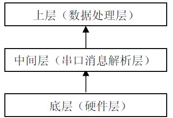
Figure 7 system architecture
2.2 Low-level module design
The underlying module sends data to the Node1, Node2, Node3, Node1, Node2, and Node3 nodes through the Move node to extract the RSSI values ​​from the Move node and encapsulate the values ​​with their SOURECE_ADDRESS values ​​into the data fields and forward them to the Sink wireless through the Forward node. Gateway node. The underlying module structure is shown in Figure 8:
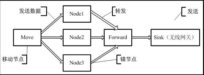
Figure 8 bottom structure 2.3 middle layer module design
This layer is mainly responsible for receiving serial port messages from the bottom layer. The focus of this layer is to parse the contents of the serial port data packet, obtain the RSSI value of the node in the data packet, the anchor node ID number and other information, and hand it to the upper layer for processing.
2.4 Upper module design
In this paper, the upper module of the wireless sensor network-based crowd anomaly activity video surveillance system is divided into the following six sub-modules:
Serial port configuration module: This module mainly configures the parameters of the serial port. When different gateways are connected to the PC, different serial ports are configured to enhance the scalability of the system.
Real-time monitoring module: This module is mainly responsible for displaying the trajectory information of the mobile node in the wireless sensor network in real time in the monitoring screen; the user understands the concept of the trajectory by clicking the display sample trajectory; clearing all trajectory information on the screen by clearing the trajectory operation; The user can set the dynamic refresh period of the trajectory data by adjusting the display refresh period; if the refresh period is set too long, the trajectory is refreshed by the manual refresh button to observe the estimated information of the mobile node in real time.
History playback module: This module plays back the historical track of the mobile node mainly according to the user's settings. The user plays back the trajectory information of the mobile node at a specific time according to his own requirements, such as playing back a day, a period of time; a period of time in a few days, a few days, or a track information of the monitored person at a precise time. In addition, the module provides a function of setting a playback period. The user sets the number of mobile node location information and the playback period for each playback according to his own needs, and the system will feed back the number of records in the database in the time period that the user queries, the user. Through the system, the number of records that need to be played back and the number of records to be played back can be clearly known.
Historical data query module: This module is mainly responsible for the query function of historical data. The module includes three functions: personnel position/trajectory general query, personnel position/track advanced query, and historical alarm information query. The person position/track advanced query mainly searches the trajectory information of the person according to the time period information input by the user, and the user queries the trajectory information of one day, one day, several days, several days or a precise time according to the demand. . In addition, this part also provides some other functions, such as the user clicking a point in the display track area, the coordinates of the click point in the drawing area, the coordinates in the actual area corresponding to the coordinate, and the query personnel appear in the actual coordinates. The number of times will be listed to display. Another important function of the historical data query module is the query function of historical alarm information. This feature allows the user to view all of the alarm information, ie all non-secure areas of the monitored person. In addition, the system provides the ability for users to delete selected alerts based on their needs.
Non-secure domain setting module: This module is mainly responsible for the setting of non-secure domains. The correct setting of the non-secure domain plays an extremely important role in the automatic alarm function of the system and the reliability of the system. Therefore, only users with set permissions can set up non-secure domains. If the person being monitored appears in a non-secure area, the system will trigger an alarm. A non-secure domain defines the radius of a non-secure domain's central and non-secure domains, and all points in that non-secure domain trigger an alert. This module allows users with permissions to modify, add, delete, and query non-secure domains based on actual needs.
Personnel Information Guide Module: This module mainly implements statistical work on historical data. The user queries the time that occurs in the specified area according to the requirements. In addition, the module also provides the function of querying the area where the monitored person appears in the specified time. In the time query form that appears in the specified area, the user sets the area to be queried or according to the time period to be queried, the query result will display the number of all queried records. In addition, this part provides other functions. For example, the user can obtain the number of times that the monitored person appears every hour and the proportion of each hour of the hour in the 24 hours per day, so that the user can easily obtain the most frequently monitored personnel in the designated area according to the result of the query. time. In the location information query function in the specified time, the user inputs the time period to be queried, and after obtaining the query result, the user clicks any query result to obtain the number of times the clicked point corresponds to the monitored person.
Alarm and record field module: alarm and record field module: This module provides alarm and record function on site. The system automatically triggers the alarm when the person is found in the non-security domain and performs the recording operation for a period of time. In addition, the system provides the ability to deactivate the alarm or end the live recording.
3 system implementation
3.1 System Development Environment
This system requires the use of a camera, micaz node and wireless gateway. Figure 9 shows the main hardware facilities used in the system, from left to right, micaz node, wireless gateway, camera. The wireless gateway is connected to the PC through a serial port, and the micaz nodes communicate with each other wirelessly, and the camera is responsible for recording the scene.
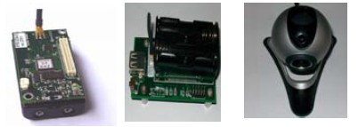
Figure 9 hardware facilities
3.2 System display
Figure 10 shows the main operation interface of the system. Users can enter the sub-module interface to perform related operations.
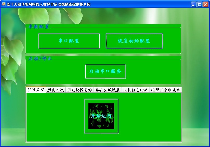
Figure 10 system operation main interface
Figure 11 shows the real-time monitoring screen of the track information of the monitored personnel:
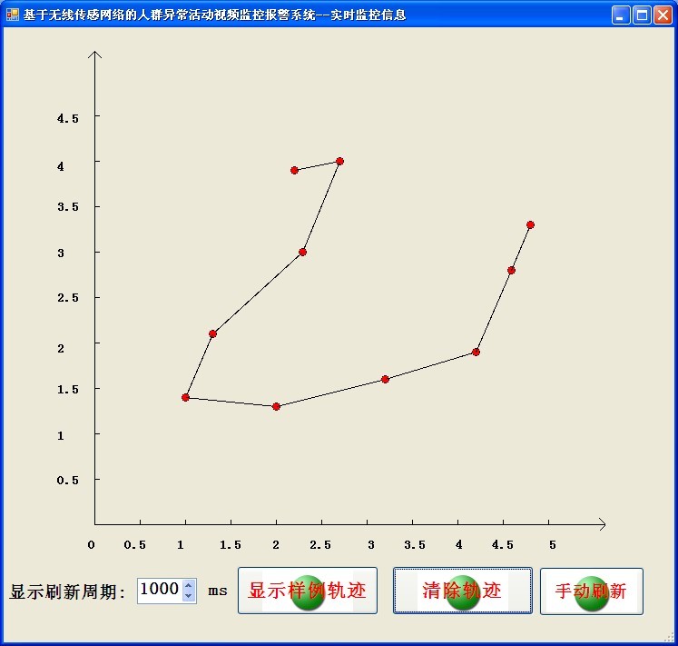
Figure 11 real-time trajectory monitoring
Figure 12 shows the playback of real-time trace information.
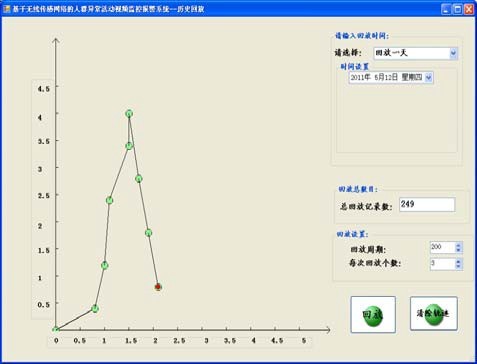
Figure 12 Historical data playback
Figure 13 shows the non-secure domain setup diagram.
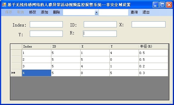
Figure 13 Non-secure domain settings
Figure 14 shows the time that the monitored person appears in the designated area.
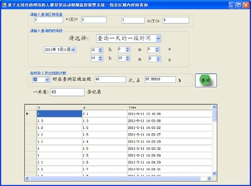
Figure 14 Time query of the person appearing in the specified area
Figure 15 shows the results of an advanced query of historical trajectory data.
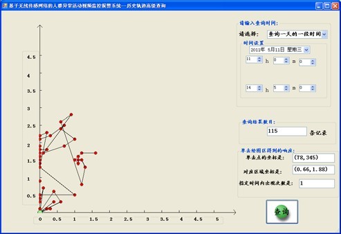
Figure 15 Historical Track Advanced Query
Figure 16 shows the recording of the scene after the system automatically alarms.
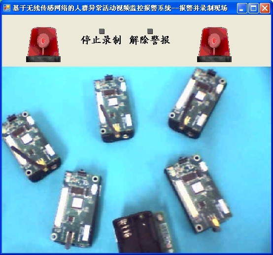
Figure 16 Alarm and recording the scene
4 Conclusion
Based on the wireless sensor network positioning technology, this paper designs a video surveillance system for crowd abnormal activities. Aiming at the problems of monitoring blind spots in the traditional video surveillance system, the system designed in this paper locates the personnel through the received signal strength of the sensor node RF chip; by setting up the non-security domain to monitor and identify the abnormal activities of the personnel, when abnormal activities occur, Automatic alarm and video recording on site. The system designed in this paper effectively avoids the occurrence of monitoring blind spots, and the automatic alarm function improves the working efficiency of the monitoring system. Looking into the future, the security, efficiency and intelligence of video surveillance systems will remain a key research direction.
references:
[1]. GPRS datasheet http://
[2]. PC datasheet http://+_2043275.html.
Laminated Glass is produced when two or more glass lites are permanently bonded with one or more plastic interlayers (PVB) using heat and pressure. The glass and interlayers can be a variety of colors and thicknesses. Laminated glass is often called [safety glass" because it meets the requirements of various code organizations. Laminated glass can be broken, but the fragments tend to adhere to the plastic layer and remain largely intact, reducing the risk of injury. Laminated glass can be incorporated with heat-strengthened and Tempered Glass to further increase impact resistance.
Triple toughened laminated glass is consisting of three panes of toughened glass and two layers of PVB or SGP film of thickness above 0.76mm. Glass and film bonded together, then compressed in autoclave to connect the glass and film firmly. Triple tempered laminated glass provide high level of protection for any forms of glass breakage.
Triple Laminated Glass is a kind of laminated glass which three panels of glass laminated, high strengthen, more safety, it can be Clear Laminated Glass, color tinted laminated glass, Low Iron Laminated Glass, printed laminated glass, made on project design request.




Laminated Toughened Glass, Jumbo Size Laminated Glass, Ultra Clear Laminated Glass, Low Iron Laminated Glass
Shanghai Lead Glass Co.,Ltd , https://www.leadglaze.com