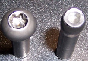
 Foreword: Due to the competition in developing countries and the development of China's fastener industry, the demand for complex and non-standard parts is constantly increasing. In order to meet the strong market demand, enterprises not only strengthen the training and training of engineering personnel, but also introduce the industry. In addition to the new technology and the introduction of foreign advanced equipment, we must develop new products and improve the ability of mold design. The successful development of finite element analysis (FEA) technology enables enterprises to avoid expensive testing and error development, greatly shortening the time for products to be put on the market, significantly prolonging the service life of molds, and understanding the process flow of engineers. Cognition continues to improve. It is also particularly helpful when discussing with customers about changing production options. For example, when a product can be produced by cold forging rather than machining, it has the ability to prove to customers through simulation analysis and simulation video. The advantages of the cold forging process.
 Background: In 2010, Shanghai Shangbiao Automotive Fastener Co., Ltd. took the lead in using the eesy-2-from software system of the German CPM company's simulation production process and optimized process design. The German CPM company provides professional software in addition to the use of software. In addition to training, relevant technical training is also provided. Below we use a series of simulation case studies and analysis to further prove and feel the practicality and accuracy of "Finite Element Analysis".
Key words: cold forging finite element analysis
Case Study: The following is a case study of product "37-3" to describe how this production process is optimized.
The equipment for the production of this product is the JBF-13B4S four-station bolt forming machine. Material is SWRCH35K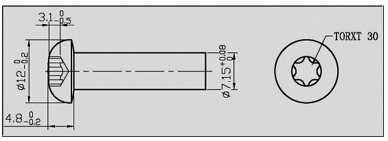
Figure 1 shows the drawing of the product Figure 1: "37-3" product drawing
One of the problems faced in the production of this product was that it was found that the part of the T30 punch used to form the groove was extremely easy to break, and the mold life was only over one hundred pieces. The productivity is extremely low and it is not possible to produce normally. After inquiry, it is known that the product has a long life in the mold.
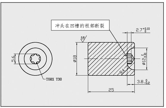
Figure 2: The punch breaks at the root of the groove
Another problem is that there is also a tendency for material accumulation, i.e., stacking, to occur in the portion of the groove depending on the preform. The cause of this phenomenon is not very clear. Therefore, the work for this product is not only to extend the life of the mold but also to ensure that the occurrence of the overlay is avoided.
The initial cold forging results are shown in Figure 3 in the Successful introduction of FEA at SQB.
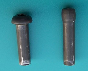
Figure 3: Initial cold forging results (old design)
It is obvious that the preforming in the first step is not sufficient. Even if you try to make a pre-groove in the first step (shown in Figure 4), the life of the mold is still not improved and it is still very easy to break.
A potential tendency for a crease to appear at the groove can be seen in Figure 4.
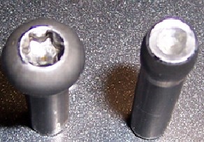
Figure 4: Cold forging results with pregrooves
Let us try to use the finite element analysis FEA technology eesy-2-form simulation software to study and understand this process.
The image of Figure 5 shows the results (shape) of the simulated groove preform. The results of the simulation also show that there are folds at the grooves. Figure 6 shows the actual product with grooves. It can be clearly seen that the results of the simulation are very accurate. The depth and position of the crease are exactly the same as the actual part. Successful introduction of FEA at SQB
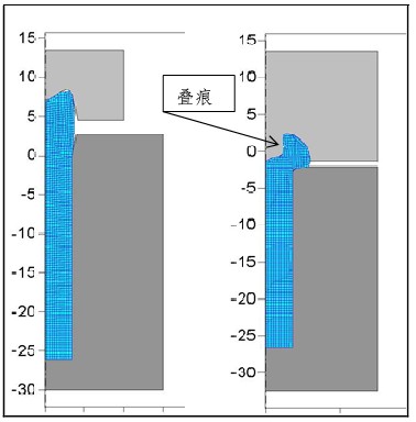
Figure 5 two process groove forming
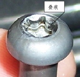
Figure 6 shows the stack marks at the grooves very accurately displayed in the simulation results.
A more detailed analysis of the simulation results helps engineers better understand material flow.
Figure 7 is a simulated image of the second process mold position movement process, clearly showing and explaining how the material flows.
Successful introduction of FEA at SQB
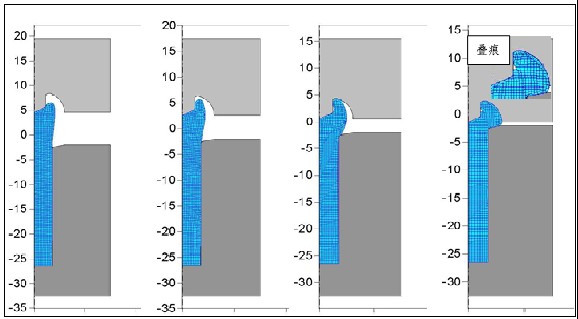
Figure 7: Mold location during forging
From such a simulated image, it can be easily and clearly understood that the material first contacts the end of the groove punch and is then pushed back to form the shape of the head. There is no radial pressure on the stem of the groove. The radial flow of material is from the tip of the punch and the end of the punch to the head of the product, not from the stem. This leads to the appearance of the crease. In the stress analysis diagram of the simulation results of Fig. 8, it is shown that the tip pressure at the plum blossom punch is very high. It also shows that the material (SWRCH35K) is overloaded, the highest value is 3158 MPa, which will cause plastic deformation of the material when there is no load on the punch rod. This causes the shear stress at the end of the plum punch to cause premature failure of the punch.
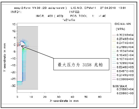
Figure 8: Right angle stress values ​​(pressure) on the die and master
The engineer modified the preform by a better understanding of the material flow. That is, the head height is reduced and the head width is increased. No pregroove is required.
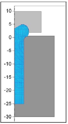
Figure 9 shows the selected new preform
Successful introduction of FEA at SQB
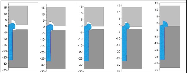 Figure 10: Deformation of the second order (new design) Figure 10 shows that the filling of the material does not appear to be superimposed in the new design.
 A lower value was shown in the right angle stress analysis of the punch surface (Fig. 11). Moreover, the stress is not at the end of the groove of the punch but at the stem.
Successful introduction of FEA at SQB
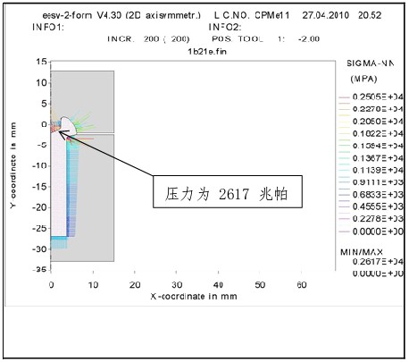
Figure 11: Right angle stress on the punch (new design) (maximum 2617 MPa)
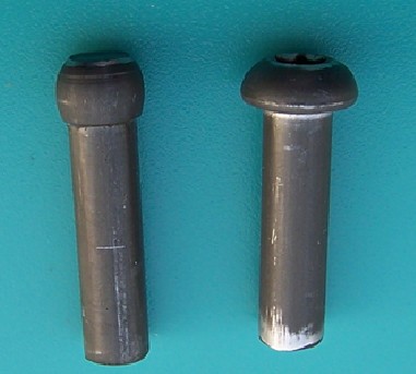
Figure 12: Product sample (new design)
Successful introduction of FEA at SQB
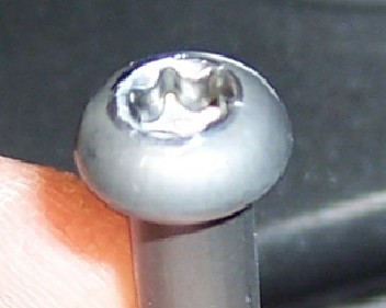
Figure 13: Product sample (new design): no overlap
The optimized process shows a perfect shape, material creases no longer appear, and die life is significantly extended.
to sum up:
After optimization, the product has an increase in product productivity from more than 100 pieces to more than 10,000 pieces and 140 pieces per minute.After a short period of training and practice on finite element analysis (EFA) eesy-2-form simulation software, engineers can effectively apply new technologies to their actual work. In this case, the preforming process was optimized to make the material flow more ideal, the load on the mold was lower and the mold life was significantly longer.
references:
[1] GH Arfmann, M Twickler "eesy" simulation software used by German CPM computer, metal forming process design, Metal Materials Technology Co., Ltd. Herzogenrath, Germany, 2010
shower filter head,head spray shower,rainfall shower head,ionic shower head,telephone shower head,shower head set gold
Yuyao Gaobao Sanitary Ware Factory , https://www.gurberry.com